Aerial data precision is defined by the mathematical alignment of digital pixels to real-world coordinates. For construction, land development, and property management in Southwest Florida, errors in this alignment result in distorted orthomosaics, inaccurate volumetric data, and failed thermal inspections. High-resolution imaging is more than a visual asset; it is a technical dataset that requires strict adherence to flight physics and sensor calibration.
When precision is compromised, the financial consequences manifest as rework, missed structural defects, or litigation-grade documentation failures. Understanding the mechanics of aerial data capture allows project managers to transition from "taking pictures" to "gathering intelligence."
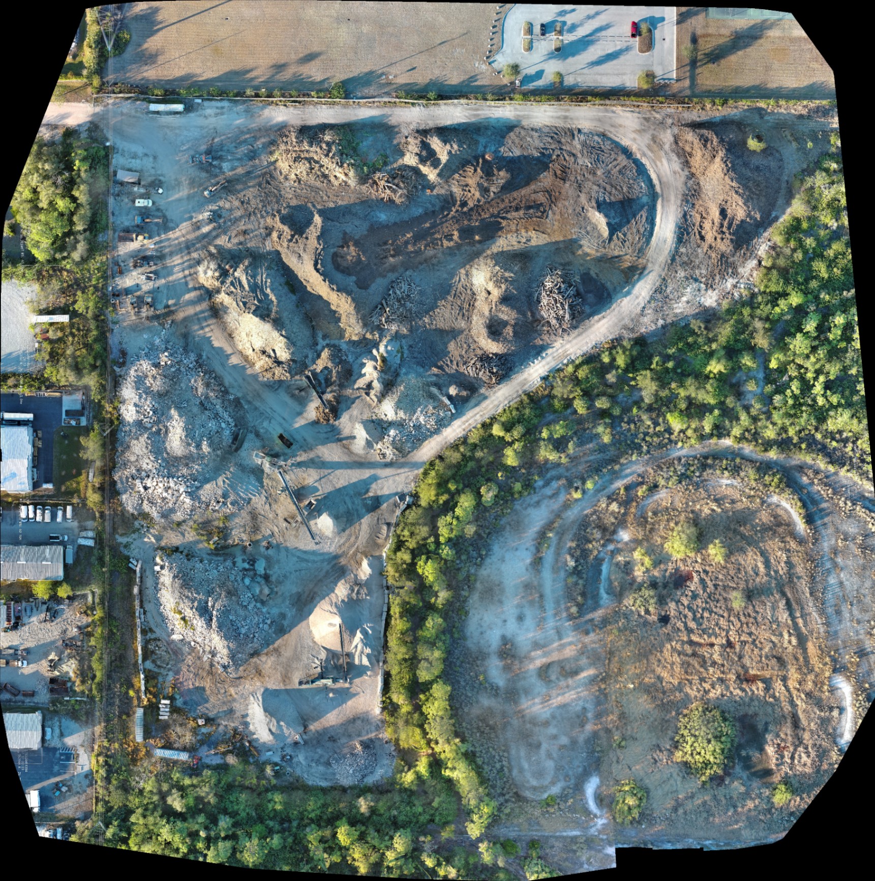
1. Poor Ground Control Point (GCP) Placement
Ground control points are physical markers on the ground with known coordinates used to "pin" aerial imagery to the earth's surface. Without GCPs, a drone relies solely on its internal GPS, which can result in vertical accuracy deviations of up to 15 meters.
Why It Matters
- Vertical Drift: On large land development sites, cumulative errors in a drone’s pitch or roll can introduce tens of centimeters of error across the model.
- Absolute Accuracy: While relative accuracy (the distance between two points in a model) may look correct, absolute accuracy (the position of the model relative to the rest of the world) will be flawed.
The Solution
Strategically place GCPs across the survey area using survey-grade GNSS equipment. Points should be spread evenly, including the center and edges of the flight path. Measuring each point twice: once before and once after the flight: ensures that any readings above 0.1 ft are identified and discarded.
2. Insufficient Image Overlap
Photogrammetry relies on matching common points across multiple images to triangulate depth and position. Capturing imagery with inadequate frontlap and sidelap results in "holes" in 3D models and blurred sections in orthomosaics.
Why This Matters
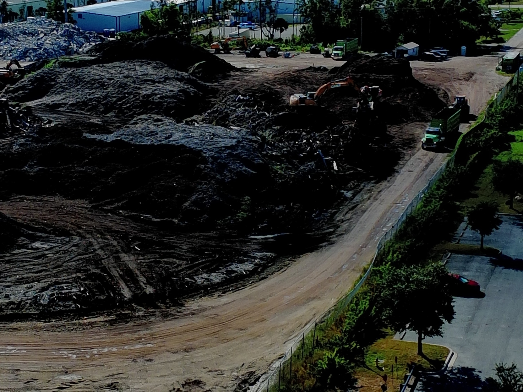
Insufficient overlap ruins volumetric calculations. If a software cannot find enough matching pixels between photos, it cannot accurately render the slopes of a stockpile or the depth of an excavation pit.
The Technical Standard
For high-precision drone mapping, missions should be configured with at least 85% frontlap and 80% sidelap. In areas with dense vegetation or uniform terrain (like Southwest Florida’s sod farms), increasing overlap to 90% helps the stitching algorithm find unique features.
3. Neglecting Sensor Calibration and Technical Specs
Using consumer-grade hardware for enterprise-level data leads to "soft" data that lacks the clarity needed for technical analysis. Even high-end platforms like the Autel Robotics EVO Lite 6T Enterprise (EVO Lite 640T) require pre-flight diagnostics to ensure the 50MP visual camera and 640×512 thermal sensor are performing optimally.
Why This Matters
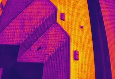
Thermal imaging for facility maintenance depends on a sensor’s pixel pitch. A 12um pixel pitch provides superior thermal sensitivity, allowing for the detection of minor temperature variations that indicate moisture intrusion or electrical overheating. If the sensor is not calibrated to the current atmospheric conditions (humidity and ambient temperature), the data becomes unreliable.
The Solution
Perform a full sensor calibration and diagnostics check before every flight. This includes verifying GPS signal strength, compass calibration, and camera gimbal balance.
ROI Advantage: Technical Specs
| Feature | Enterprise Standard (EVO Lite 640T) | Impact on Data |
|---|---|---|
| Thermal Resolution | 640 × 512 | Detects smaller anomalies at greater distances |
| Pixel Pitch | 12um | Higher sensitivity for moisture/heat loss |
| Visual Resolution | 50MP | Crystal clear orthomosaics for planning |
| Frame Rate | 30Hz | Smooth thermal data capture without motion blur |
4. High ISO Settings and Motion Blur
In an attempt to capture data in low-light conditions, many operators increase the ISO setting. Setting ISO above 400 introduces significant digital noise into the source imagery.
Why It Matters
Digital noise creates "grain" that photogrammetry software struggles to process. When the software cannot distinguish between a real-world feature and a digital artifact (noise), the resulting 3D model will have "floaters" or distorted surfaces.
The Solution
Keep ISO at or below 400. In lower light, it is preferable to slow the flight speed and use a faster shutter speed than to compromise the sensor's native clarity. High-resolution results depend on clean, uncompressed RAW data.
5. Misunderstanding Absolute vs. Relative Accuracy
A common mistake in aerial data is assuming that a "pretty" map is an accurate one. There is a fundamental difference between relative accuracy and absolute accuracy.
The Distinction
- Relative Accuracy: The distance between point A and point B on your map is correct (e.g., a 10-foot sidewalk measures as 10 feet).
- Absolute Accuracy: The coordinates of point A and point B match their true location on the Earth (e.g., the sidewalk is actually where the map says it is).
Why This Matters
For industrial applications, relative accuracy might suffice for calculating the volume of a dirt pile. However, for land development and site planning, absolute accuracy is required to ensure that new infrastructure aligns with existing utilities and property boundaries.
6. Poor Flight Planning and Suboptimal Camera Angles
Flying at the wrong altitude or using the wrong gimbal pitch can render a dataset useless for specific deliverables. For example, capturing a 2D orthomosaic requires a nadir (90-degree) camera angle, while 3D modeling often requires oblique (30 to 45-degree) angles to capture the vertical faces of structures.
Why This Matters
If the flight boundary is set exactly at the edge of the property, the "edge" photos will not have enough overlap to be processed accurately. This leads to warping and "melting" at the borders of the map.
The Solution
Plan flight boundaries at least 100 feet beyond the area of interest. This provides the necessary buffer for the photogrammetry software to "anchor" the edges of the site with high-confidence data.
7. Incorrect Capture Timing for Thermal and GNSS
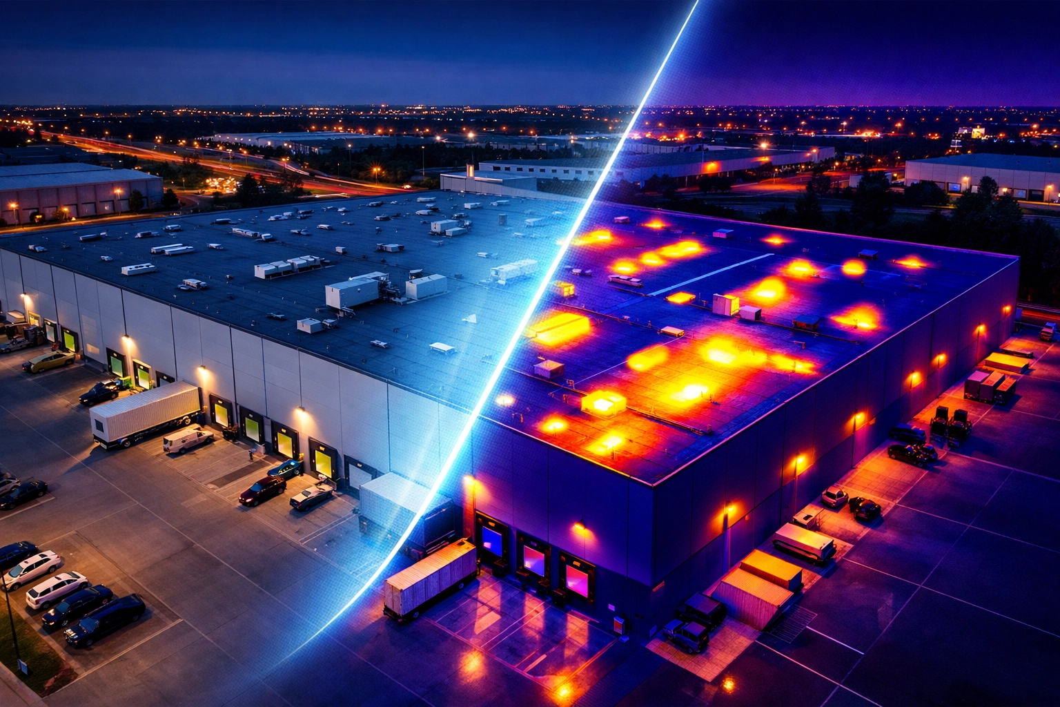
For thermal imaging, timing is everything. Conducting a thermal roof inspection in the middle of a hot Florida afternoon will result in "solar loading," where the sun's heat masks the internal thermal anomalies you are trying to find.
Why This Matters
Thermal results indicate anomalies like trapped moisture or insulation gaps. If the surface is too hot from direct sunlight, those anomalies disappear. Similarly, for mapping, failing to account for the time it takes for GNSS (Global Navigation Satellite System) receivers to reach a "fixed" state leads to erratic coordinate data.
The Solution
Conduct thermal inspections during "thermal crossover": typically after sunset or early in the morning when the structure has reached a steady state. For mapping, ensure that all AeroPoints or ground sensors have at least 45 minutes of data capture to allow for proper post-processing correction.
ROI Advantage: Why Precision Matters for Southwest Florida Businesses
Investing in high-resolution, professionally captured aerial data is a proactive strategy for risk mitigation.
- Construction: Avoid costly grading errors by using high-resolution orthomosaics for progress monitoring.
- Facility Management: Identify roof leaks via thermal inspection before they cause structural damage.
- Real Estate: Use 50MP visual data to highlight property boundaries and amenities for luxury listings.
By avoiding these seven common mistakes, Cape UAV ensures that every flight delivers actionable data rather than just aerial photos. Our use of the Autel Robotics EVO Lite 6T Enterprise: operated by FAA Part 107 certified pilots: guarantees that the technical specifications meet the rigorous demands of industrial and commercial clients.
Important Disclaimer
Mapping Disclaimer: Our data is for planning purposes and is not a substitute for a licensed land survey.
Thermal Disclaimer: Thermal results indicate anomalies and are not a substitute for evaluation by a licensed professional.
For more information on how precision aerial data can support your next project, visit our FAQ page or contact us for a consultation.
Important Disclaimer
Our data is for planning purposes and is not a substitute for a licensed land survey. Thermal results indicate anomalies and are not a substitute for evaluation by a licensed professional. Autel Robotics is a trademark of its respective owner; Cape UAV is not affiliated with or endorsed by Autel Robotics. Results depend on environmental conditions.